Modern industrial automation relies on extensive cable networks that supply electrical power to actuators and motors while carrying control signals between sensors, programmable logic controllers, human-machine interfaces, and distributed devices. Plastic Cable Gland form the junctions where these cables terminate, join, or transition between equipment sections. They secure the connection mechanically, insulate the electrical contacts, and often provide a degree of protection against the surrounding industrial environment.
In facilities that operate continuously—whether assembling components, handling materials on conveyors, inspecting products with cameras, or coordinating robotic movements—cables experience constant vibration, occasional mechanical tension, exposure to airborne particles, humidity variations, and cleaning procedures. Plastic connectors address these conditions through their material properties and design features. The polymer housing insulates contacts, reduces weight compared to metal alternatives, and allows molded-in features such as strain relief and locking mechanisms.
The ability to disconnect and reconnect quickly supports the modular character of automation systems. Sub-assemblies, tools, or sensor groups can be serviced or replaced without rewiring long cable runs.
A standard plastic cable connector consists of two mating parts: one side carries protruding pins, the other contains corresponding sockets. Both halves use a molded plastic housing to position and protect the metal contacts. The housing material—typically a thermoplastic or thermoset compound—provides electrical insulation between adjacent contacts and mechanical support against bending or impact forces.
Metal contacts inside the housing conduct current or signals. Pins and sockets are usually made from copper-based alloys with surface treatments to maintain low resistance over repeated mating cycles. The plastic body holds these contacts in precise alignment, preventing misalignment during connection and reducing the chance of short circuits or arcing.
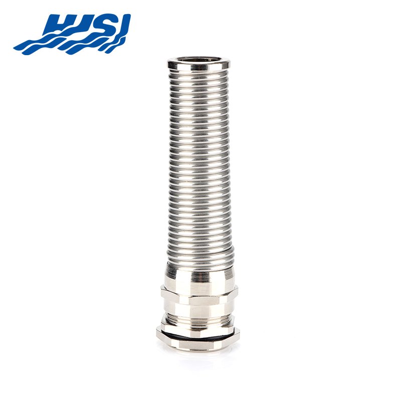
Strain relief forms an integral part of the design. A molded collar, clamp, or molded-in grip secures the cable jacket near the entry point, distributing any pulling or twisting forces across a larger area rather than concentrating them at the termination points. This feature helps prevent conductor breakage or insulation damage from repeated movement.
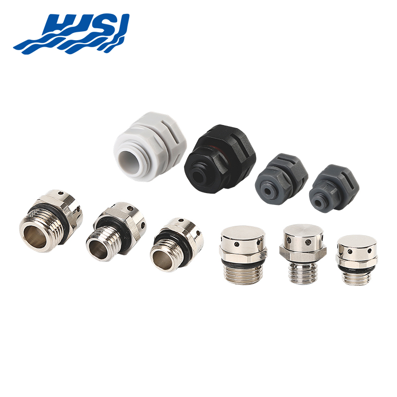
Sealing elements—such as compressed gaskets, o-rings, or molded lips—create a barrier when the connector halves are joined. In mated condition, these seals limit the entry of dust, water droplets, or process vapors into the contact area. Some connectors include additional sealing methods, such as overmolded cable entries or secondary backshells, for applications in more demanding environments.
Locking mechanisms secure the mated pair against vibration. Threaded couplings offer firm retention, bayonet styles provide quick engagement through a twist-and-lock motion, and latch systems allow one-handed operation. These locking features are frequently molded directly into the plastic housing, eliminating separate metal parts and simplifying the overall assembly.
Color coding, keying notches, or mechanical polarization prevent incorrect mating of connectors carrying different voltages, signal types, or functions, reducing installation errors in complex wiring layouts.
Plastic cable connectors offer characteristics that match the operational demands of automated production. Their lower density reduces the overall weight of cable assemblies. In applications involving continuous motion—such as articulated robots, linear transfer systems, or cable carriers—this weight reduction decreases inertial forces, supports smoother acceleration profiles, and lowers energy requirements for movement.
The material resists corrosion from exposure to cleaning agents, coolant mists, humid air, or occasional process fluids. Plastic housings do not develop surface oxidation or pitting, maintaining structural integrity and electrical performance without additional protective coatings.
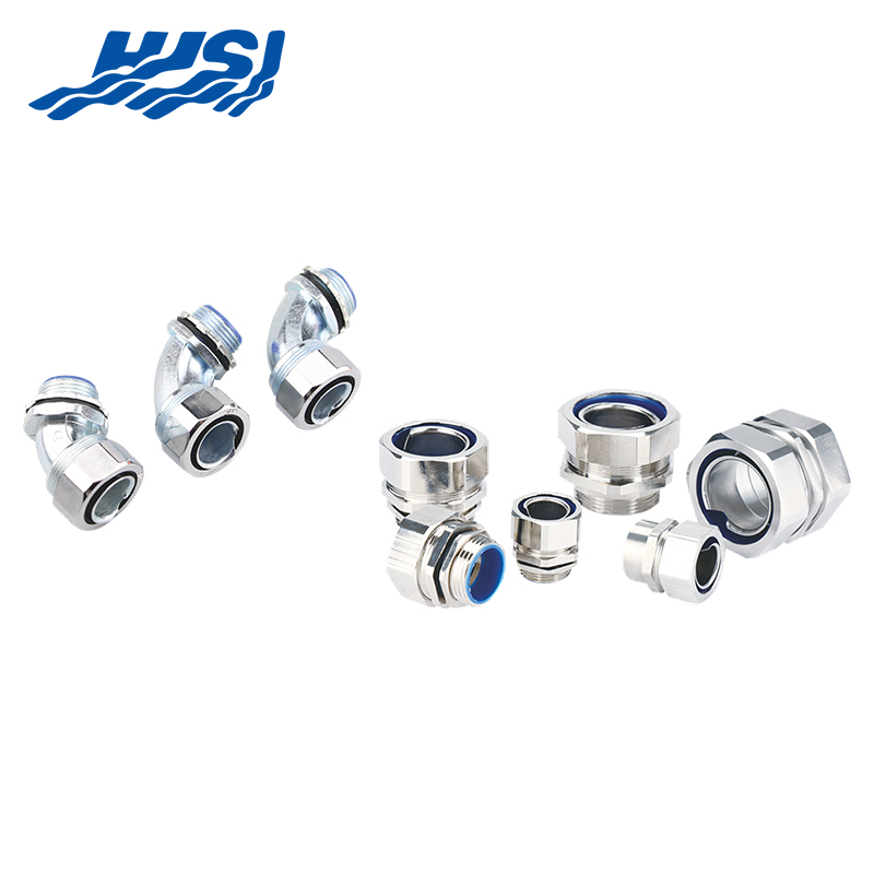
Molding technology allows intricate shapes and integrated features at reasonable cost. Connectors can incorporate angled cable entries to fit confined spaces, built-in mounting points for panel attachment, or custom strain relief geometries tailored to specific cable diameters and flex requirements.
Environmental sealing helps sustain connection reliability. Designs that block dust or liquid ingress reduce the occurrence of intermittent faults in areas subject to material dust, washdown routines, or condensation.
The insulating nature of the polymer limits electromagnetic interference coupling from nearby power lines or inductive loads. This property supports stable transmission of sensor signals, encoder feedback, and fieldbus communication in electrically noisy factory settings.
From a manufacturing perspective, injection molding produces consistent parts in large quantities. This consistency benefits large-scale automation projects where hundreds or thousands of connectors may be installed across a single facility.
| Aspect | Key Property / Feature | Benefit in Industrial Automation |
|---|---|---|
| Electrical Insulation | Polymer material insulates contacts | Reduces EMI coupling from power lines or inductive loads |
| Signal Stability | Limits electromagnetic interference | Ensures reliable transmission of sensor signals, encoder feedback, and fieldbus data in noisy environments |
| Manufacturing Method | Injection molding | Produces consistent, high-volume parts |
| Production Scale Advantage | Enables large quantities with uniformity | Supports large-scale projects requiring hundreds or thousands of connectors per facility |
Circular plastic connectors appear widely due to their symmetrical geometry and balanced stress distribution. Threaded locking mechanisms provide secure retention in vibration-heavy applications, while bayonet couplings allow faster connection in areas requiring periodic access.
Rectangular connectors feature flat housings suitable for panel mounting or dense cabinet wiring. Modular insert systems permit combination of different contact types—power, signal, coaxial, or pneumatic—within a single shell, simplifying organization in control enclosures.
Push-pull connectors emphasize ease of use. An axial push engages the internal latch; a firm pull releases it. This style suits diagnostic ports, test points, or tool interfaces where technicians need rapid connection and disconnection.
Variants designed for higher environmental protection incorporate additional sealing or overmolding around the cable entry. These handle occasional liquid contact or heavy dust loads near processing machinery.
Reinforced housings in certain models withstand greater axial forces, making them appropriate for long cable runs under tension or in applications with frequent pulling.
Selection depends on the number of contacts needed, expected environmental exposure, frequency of mating cycles, vibration levels, and available mounting space within the automation equipment.
In robotic workcells, plastic connectors join power feeds to joint motors and carry encoder signals back from end-effectors. The design handles constant bending as the arm moves through its cycles, while the built-in strain relief keeps repeated flexing from damaging the cable at the point where it enters the connector.
Conveyor setups use these connectors to tie together proximity sensors, light-beam detectors, and motor drive controls. The sealing around the mated halves blocks out the fine dust kicked up by moving products and guards against the occasional liquid splash that can occur during operation.
At assembly workstations, cables run through connectors to reach electric grippers, air-operated valves, and mounted cameras. Push-pull or quick-release styles make it straightforward to swap out tooling or fixtures when the line changes over to a different part or batch.
Packaging machinery relies on connectors to link servo drives, rejection actuators, and safety light curtains. The locking system stays engaged despite the steady vibration produced by fast, repetitive cycles.
Inside control cabinets, rectangular plastic connectors organize the field wiring coming from the floor. Their modular construction makes it easy to plug in extra I/O cards or expand the system whenever production needs grow or change.
Vision-based inspection stations connect high-speed camera cables in areas filled with electrical noise from adjacent drives and inverters. The insulating plastic body helps keep interference low so the captured images remain clear and usable for processing.
Across these different areas, plastic connectors create wiring layouts that stay flexible, allow quick service access, and support the distributed, adaptable nature of today's automated production lines.
Start cable preparation by stripping the outer jacket and inner insulation layers with precision so the bare conductors remain undamaged. Attach the contacts using crimping tools or soldering equipment, following the exact method required for that connector style.
Load the prepared contacts into the housing, paying close attention to alignment keys, color markings, or built-in polarization features that guarantee the correct orientation and prevent crossed connections.
Position the sealing rings or gaskets correctly around the cable where it enters the body so the environmental barrier remains intact once the halves are joined.
Make certain the locking mechanism snaps, twists, or threads completely into place. Anything less than full engagement leaves the connection vulnerable to working loose during machine vibration or movement.
Route the cable so it forms gentle curves near the connector rather than sharp kinks, and use clamps, ties, or protective conduits to keep tension and sagging under control along the run.
Once everything is assembled, run continuity checks to confirm the electrical circuit is complete, measure insulation resistance to verify no unintended paths exist, and visually confirm that seals are seated and locks are secure.
Apply clear labels to each connector showing its purpose, voltage class, or connected equipment. This simple step speeds up future tracing and repair work.
Following these steps during initial setup creates connections that start strong and remain dependable through normal operation.
Carry out regular visual checks to spot any cracks in the housing, color changes that suggest heat exposure, or signs of wear on latches and coupling threads. Catching these early lets you fix or replace parts before they cause downtime.
Clean off built-up dust, grease, or process residue with gentle cleaners formulated for plastic surfaces. Steer clear of aggressive solvents that can make the material brittle, swell, or turn cloudy over repeated use.
Examine the seals at each inspection. If a gasket looks flattened, torn, or hardened, swap it out right away to keep the protective barrier working as intended.
Contacts used for low-current signals sometimes collect a thin layer of oxidation after months without movement. A few deliberate connect-disconnect cycles usually wipe the surfaces clean again.
Look for evidence of overheating—soft spots, darkened areas, or slight deformation in the plastic—which points to excessive resistance or an overloaded circuit. Track down and correct the electrical problem as soon as possible.
Keep a log of every inspection, noting the date, what was observed, and any actions performed. These records reveal patterns and help plan replacements before issues become serious.
Steady, attentive care keeps connectors functioning well and plays a direct role in keeping the overall automation equipment available when it is needed.
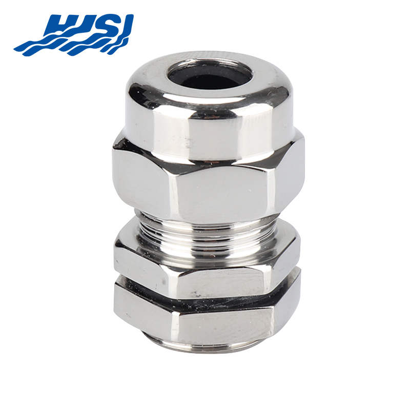
Metal-bodied connectors bring greater physical toughness and hold up better against heavy impacts or rough handling in demanding locations.
Plastic housings resist corrosion far more effectively when exposed to humid air, cleaning chemicals, or process vapors that would cause metal to rust or pit.
The lighter weight of plastic becomes an advantage in systems with constant motion, easing the load on cable tracks, robotic joints, and support structures.
High-volume molding keeps plastic connector production costs lower than machining or casting metal equivalents.
Metal enclosures generally offer stronger shielding against electromagnetic interference in electrically noisy surroundings.
Heat moves through metal more readily, helping to dissipate thermal energy, whereas plastic tends to hold heat closer to the contacts.
Deciding between plastic and metal comes down to weighing the environment's demands, mechanical stresses, electrical noise levels, thermal behavior, and overall budget for the specific installation.
Large swings in operating temperature can change how rigid or flexible the plastic remains and affect how well seals compress. Choosing a polymer grade suited to the expected range keeps performance stable.
Ongoing vibration sometimes works locking mechanisms loose over many cycles. Connectors with strong, positive-latching designs or added retention features help hold connections tight.
Certain chemicals in the factory atmosphere may slowly attack the housing or gasket material. Checking compatibility charts during the planning stage avoids long-term degradation.
| Challenge | Description / Risk | Solution / Preventive Measure |
|---|---|---|
| Ongoing vibration | Can loosen locking mechanisms over repeated cycles | Use connectors with strong positive-latching designs or additional retention features to keep connections secure |
| Chemical exposure | May gradually degrade housing or gasket material | Verify material compatibility using charts during the planning and specification stage to prevent long-term damage |
Too much current through the contacts creates heat that can soften the surrounding plastic. Matching the connector rating to the load, adding circuit protection, and watching for temperature rise prevent this problem.
Combining thoughtful material choice with routine inspections handles these issues before they disrupt production.
New polymer blends keep improving, delivering better toughness, wider temperature capability, stronger resistance to chemicals, and enhanced flame-retardant properties.
Ongoing size reduction allows more contacts to fit into smaller connector bodies, which helps in tight machine spaces where wiring density continues to increase.
Adding built-in sensors or status indicators inside connectors could provide live feedback about connection health, supporting condition-based maintenance programs.
Greater use of recycled plastics and bio-derived resins responds to growing interest in lowering the environmental footprint of manufacturing components.
These changes position plastic connectors to keep pace with factories that demand more compact, intelligent, and sustainable electrical connections.
At HJSI, the focus on plastic cable connectors for industrial automation reflects a deep understanding of the daily realities faced by production facilities worldwide. By prioritizing designs that combine reliable electrical performance with practical environmental protection and straightforward serviceability, HJSI enables engineers and operators to build cable infrastructures that remain dependable even amid constant motion, vibration, dust, and occasional moisture exposure.
This approach supports the broader goal of keeping automated lines running smoothly with reduced unplanned interruptions, giving manufacturing teams the confidence to concentrate on output quality and process improvements rather than frequent connection-related troubleshooting. Through continued emphasis on durable materials, thoughtful sealing solutions, and user-friendly installation features, HJSI contributes to automation systems that adapt more readily to changing production demands while maintaining consistent electrical integrity over long service intervals.

2nd Floor, Building 2, No. 188, Punan 3rd Road, Economic Development Zone, Yueqing City, Wenzhou City, Zhejiang Province, China

Copyright @ Zhejiang HJSI Connector Co., Ltd. All rights reserved.

China Waterproof Breathable Valve Manufacturer
 +86-15858552966
+86-13356176555
+86-15858552966
+86-13356176555

 English
 русский
 عربى
عربى