A screened cable that leaves the factory in perfect balance can become a radiating antenna by the time it is screwed into a cabinet. The degradation rarely comes from the cable itself; it comes from the way the screen is terminated, or the EMC Cable Gland is installed. Electromagnetic-compatibility (EMC) performance is therefore not a property you buy—it is a property you build, bolt by bolt, crimp by crimp. The following pages walk through the recurring errors found on construction sites, wind-turbine towers, battery halls, and rooftop solar skids. Each error is illustrated with the physical mechanism that allows interference to escape or enter, followed by a field-tested correction that can be applied with common tooling.
A shield works only if the noise current that rides on its outer surface is given a low-impedance route back to the source. That route must encircle the inner conductors completely; any gap becomes a slot antenna. Installers often strip the outer jacket, part the braid, and twist the drain wire into a pigtail that is only two centimeters long. The length sounds negligible, but at a hundred megahertz it behaves like an inductor of several tens of nanohenrys, developing a voltage drop that drives common-mode current onto the inner conductors. The pigtail therefore converts a shield into a radiator.
Remove the outer jacket without disturbing the braid. Use a non-serrated tool to push every strand back into a cylindrical form. Slide a metal gland cone or EMC ferrule over the braid so that the entire circumference is compressed against the inside of the gland body. Tighten until the braid shows slight embossing; this proves metal-to-metal contact around the full circle. The drain wire, if present, is folded back and captured under the same ferrule, not led away as a separate tail. The result is a closed coaxial path from cable screen to enclosure wall.
Cable glands are sold in dozens of styles. Installers sometimes reach for the nearest liquid-tight nylon gland because it threads easily into a thin panel. Nylon is an insulator; the moment the shield reaches the plastic shoulder, the 360° path is lost. Another variant is the brass gland with a single compression seal. Brass is conductive, but the seal is placed ahead of the thread, so the braid is pinched only at one point. Under vibration the point contact relaxes, resistance rises, and the slot re-opens.
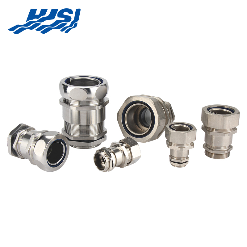
Match the gland family to the EMC label on the drawing. A proper EMC gland carries an internal cone and an external nut both made of stainless steel or nickel-plated brass. The cone bites the braid while the nut pulls the cone into the body, ensuring pressure around the full circumference. Inspect the internal parts before insertion; if the cone is missing, swap the gland rather than hoping the seal will suffice. After tightening, perform a tug test: grip the cable jacket and pull axially. A correctly seated shield will not slide under hand force.
Control cabinets contain two earth rails: a protective earth (PE) bar bonded to the enclosure, and a functional earth (FE) rail isolated from the panel for signal reference. Noise currents on the screen must reach the PE rail so they can return to the source outside the cabinet. If the screen is tied to the FE rail, the noise finds a path through circuit boards and logic grounds, creating unpredictable upsets. The error is common when installers follow a colour code instead of a schematic.
Run a temporary bonding lead from the FE rail to the PE bar during commissioning. Measure the common-mode voltage between the screen and the PE bar with a high-impedance meter. If the voltage exceeds a few millivolts, relocate the screen lug to the PE bar. Once the relocation is complete, remove the temporary bond; the FE rail can now serve its intended purpose without carrying noise.
| Issue | Cause | Correction |
|---|---|---|
| Noise on cable screen | Screen connected to FE rail instead of PE | Temporarily bond FE to PE during commissioning |
| Unpredictable circuit upsets | Noise returns through logic and circuit boards | Measure common-mode voltage; relocate screen to PE if needed |
| FE rail misuse | Installer follows color code, not schematic | Remove temporary bond after verification; FE serves intended purpose |
After the gland is secured, installers often cut the outer jacket back by twenty centimetres to allow individual cores to reach terminal blocks. The exposed length becomes an unintended monopole. Radiated immunity tests reveal the problem when a ten-volt-per-metre field induces milliamps on the unbalanced tail, flipping digital inputs. The same tail radiates when fast edges from switching power supplies travel outward.
Limit the unscreened length to the minimum required for bending radius. Slide a copper-foil wrap or a split ferrite core over the tail if more length is unavoidable. The foil is soldered to the gland body at one end and to a copper bus-bar at the other, restoring a pseudo-coaxial shape. Ferrite adds impedance in series, suppressing common-mode current without affecting differential signals. Both fixes are retrofittable during commissioning if emissions or immunity tests fail.
A multi-core cable may carry pairs destined for analogue inputs, encoder pulses, and brake control. Installers sometimes land the analogue pair on an isolated terminal, the encoder screen on the PE rail, and the brake screen on the motor frame. The three screens now sit at different potentials, and noise couples from one to another through stray capacitance. The result is sporadic encoder counts or phantom brake releases.
Adopt a single-point philosophy for each bundle. If the design demands isolation for analogue signals, use a separate cable rather than mixing philosophies inside one sheath. Where mixing is unavoidable, terminate all screens at the gland and float the inner circuit ends. Add a 1-nanofarad ceramic capacitor from the floated end to PE for radio-frequency continuity while maintaining DC isolation. The capacitor provides a low-impedance path at the frequencies that matter for EMC, without creating unwanted DC loops.
Steel-wire armour is meant for mechanical protection, but installers occasionally use it as the sole earth return. Under fault conditions the armour carries heavy current, and its impedance is ten times higher than a copper conductor. The voltage drop appears between remote earthed equipment, driving current onto signal screens that were never designed for power. Emissions rise, and immunity falls.
Run a separate copper protective conductor alongside the armoured cable. Bond the armour to the same bar at both ends so that it shares, rather than monopolises, the fault current. Use an EMC gland that grips both the braid and the armour; the cone inside the gland bites the braid while a clamping ring captures the armour wires. The two paths now run in parallel, lowering overall impedance and reducing the voltage that could couple onto nearby screens.
Spare cores are common in control cables. Installers trim and tape the unused pairs, leaving their screens open at both ends. The floating screen acts like a receiving antenna for electric fields and a transmitting antenna for common-mode noise generated inside the cabinet. During immunity testing the floating screen resonates at a quarter wavelength, injecting unexpected energy into active pairs.
Terminate every screen, even on spare pairs. If the spare must remain isolated for future use, bond its screen to PE at the cabinet end only. At the field device end, cap the screen with heat-shrink to prevent accidental contact. The single-point bond prevents the screen from becoming a dipole while preserving the option to reconfigure the pair later.
| Issue | Cause | Correction |
|---|---|---|
| Floating cable screen | Unused pairs left unconnected at both ends | Terminate screens properly |
| Noise interference | Floating screen acts as antenna for electric fields | Bond screen to PE at cabinet end |
| Resonance during testing | Screen behaves like a dipole | Use single-point grounding |
| Accidental contact | Exposed screen at device end | Seal with heat-shrink protection |
Flat screened cables offer neat routing under raised floors, but a fold tighter than ten times the cable height kinks the braid. The kink separates strands, creating a slot that radiates broadside to the fold. Crosstalk increases between adjacent flat cables, and differential signals pick up common-mode noise.
Maintain a bend radius larger than ten times the minor axis of the flat cable. If space is tight, transition to round screened cable before the bend. Use a formed aluminium channel as a mechanical former; the channel also acts as an additional shield. Where a fold is unavoidable, cut the cable and insert a short round jumper that preserves 360° continuity.
Conduit provides mechanical protection and can extend the cable shield if it is bonded at both ends. Installers sometimes push a screened cable into conduit but forget to attach a bonding bushing. The conduit then floats at radio frequency and behaves like a sleeve antenna. Emissions measurements show spikes at the conduit resonant length.
Install a stainless steel bonding locknut or bushing at each conduit entry. Use a short braid or copper tape to join the bushing to the cabinet earth bar. Ensure that the conduit run is electrically continuous; if joints use compression couplers, add a jump wire across each joint. After bonding, rerun the emissions scan; the peaks that disappeared confirm the conduit was the unintended radiator.
Cable trays are convenient highways, but each segment is bolted to steelwork that may not be electrically continuous at high frequency. A long tray can become a loop antenna if the screen of a cable bonded at one end finds a different return path through the tray. The loop area is measured in square metres, and the resulting magnetic field couples into nearby control wiring.
Bond every tray section with a short braid rated for fault current. At intervals of every three metres, connect the tray to the PE network so that no section can float. Where trays cross expansion joints, use braided jumpers that tolerate movement without cracking. After installation, clamp a current probe around the tray and inject a calibrated RF current; if the probe detects significant current, add more bonds until the reading falls.
Ferrite cores are popular cures for high-frequency noise, but they work only if the common-mode current is forced to pass through the ferrite. Installers sometimes clamp a ferrite on the cable jacket without ensuring that the screen beneath is bonded immediately after the ferrite. The noise current bypasses the ferrite through the unbonded screen and continues to radiate.
Place the ferrite directly ahead of the gland entry. Bond the screen immediately after the ferrite so that any current on the outer surface must travel through the high-impedance core before reaching the enclosure. If multiple cables enter the same gland, use a single large ferrite around the bundle; individual small cores allow field cancellation between cables and reduce effectiveness.
Enclosures are powder-coated for corrosion protection, but the coating is an insulator at radio frequency. A gland nut tightened against painted metal forms a capacitor of a few picofarads—low enough to pass megahertz signals. The screen noise then couples onto the panel and re-radiates.
Remove paint under the gland nut with a star washer or a ring of emery cloth. The washer bites through the coating and establishes metal-to-metal contact. Apply a thin layer of non-acidic joint compound after cleaning to prevent moisture ingress. Re-torque the nut after twenty-four hours; paint creep can loosen the joint.
Power cables carry hundreds of amperes at switching frequency. If a small signal cable shares the same gland, the power screen noise can couple onto the signal screen through the common impedance inside the gland body. The installer sees only one hole in the panel and thinks space is saved; the EMC test sees a new coupling path.
Separate glands for power and signal categories. If separation is impossible, use a double-deck gland that maintains individual cones for each cable. The metal wall between decks acts as a shield. After installation, measure common-mode voltage between the two screens; if it exceeds a few millivolts, add an external bonding lead or relocate one cable.
Crimp tools have multiple dies, and an installer in a hurry may use the next smaller die to ensure a tight fit. The excess pressure cold-welds the braid strands and creates micro-cracks. Over time vibration opens the cracks, resistance rises, and the slot antenna reappears.
Select the die recommended by the gland supplier. Perform a pull test on the first sample; the crimp should survive a tensile load equal to the cable’s own weight without visible separation. Inspect the crimp with a hand lens; strands should remain rounded, not flattened into a ribbon. If in doubt, cut off the crimp and start again—replacing a gland is cheaper than re-testing the entire cabinet.
After every screen is landed, a quick verification saves hours in the chamber. Clip a milliohmmeter between the cable screen at the field device and the PE bar in the cabinet. The reading should be below the value calculated from cable length and braid conductivity. A high reading indicates a hidden pigtail, a loose cone, or a painted panel. Correct the fault immediately; once the cabinet is populated, access becomes difficult.
Behind every quietly passing immunity test stands a cone-shaped ferrule, a stainless steel gland body, and a braid that was coaxed back into a perfect cylinder—hardware that rarely carries a brand name visible from the outside.
Zhejiang HJSI Connector Co., Ltd. keeps that low-profile discipline alive by machining, polishing, and pressure-testing each cable gland so the installer can concentrate on geometry instead of guesswork. When their parts leave the dock, the 360° rule is already cast into the metal; the only remaining task is to tighten the nut until the braid shows the faint emboss that signals an unbroken coaxial path. In that moment, the factory floor in Zhejiang and the tower base in the North Sea share the same quiet contract: let noise currents stay on the outside, let electrons travel on the inside, and let the energy transition proceed without a single preventable spike on the spectrum analyser.

2nd Floor, Building 2, No. 188, Punan 3rd Road, Economic Development Zone, Yueqing City, Wenzhou City, Zhejiang Province, China

Copyright @ Zhejiang HJSI Connector Co., Ltd. All rights reserved.

China Waterproof Breathable Valve Manufacturer
 +86-15858552966
+86-13356176555
+86-15858552966
+86-13356176555

 English
 русский
 عربى
عربى