A solar module, a wind nacelle, and a battery rack each generate or store energy, yet none can deliver that energy without a protected pathway for the conductors that carry it. Across fields, rooftops, ridgelines, and storage yards, raceway systems form those pathways, and the modest components that join each length of raceway are conduit connectors—augmented at every entry point by a Conduit Gland that clamps the outer jacket, relieves tension, and seals the boundary between the external environment and the energized core. These pieces lock one segment to the next, turn corners, branch, rise from soil to enclosure, and anchor the entire assembly to the equipment that controls, converts, or collects the power. Their task is to keep the interior of the raceway free from water, dust, ice, chemical vapor, and mechanical shock while allowing the system to expand, contract, and be reconfigured over decades.
Sunlight delivers both energy and ultraviolet exposure. Wind brings steady vibration and, in coastal districts, salt. Battery rooms add warm, circulated air that can carry trace gases. Soil around trench lines may be expansive clay, frost-heaving silt, or corrosive reclaimed farmland. Conduit connectors must tolerate these stresses without loosening, cracking, or losing grip on the bonding path that carries fault current. Designers begin by mapping the micro-climates along each cable route: the rooftop parapet that bakes in afternoon sun, the shaded north-side trench that stays damp, the tower wall that sways slightly in high winds, the transition from outdoor ambient to conditioned battery hall. Each zone suggests a material, a sealing style, and a mounting detail for the connectors that will live there.
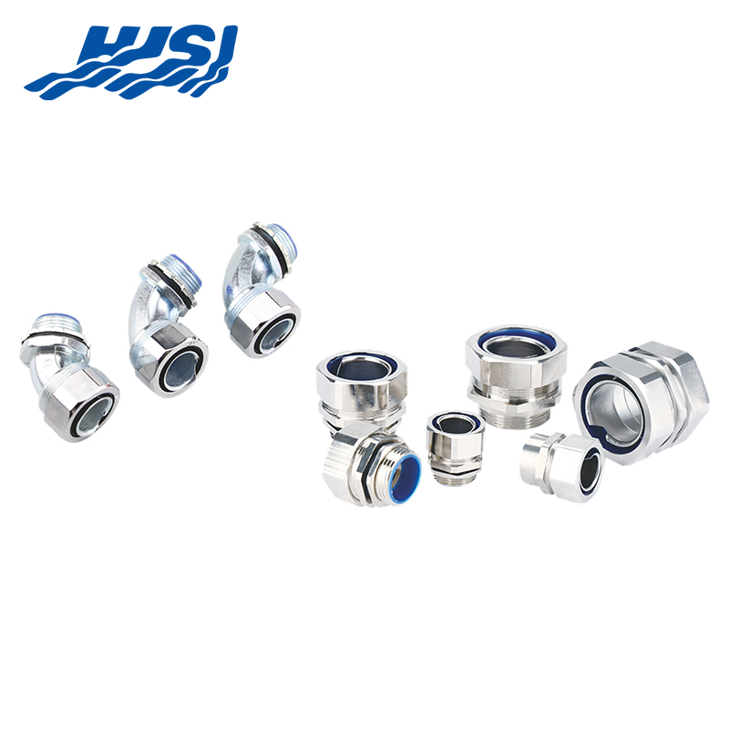
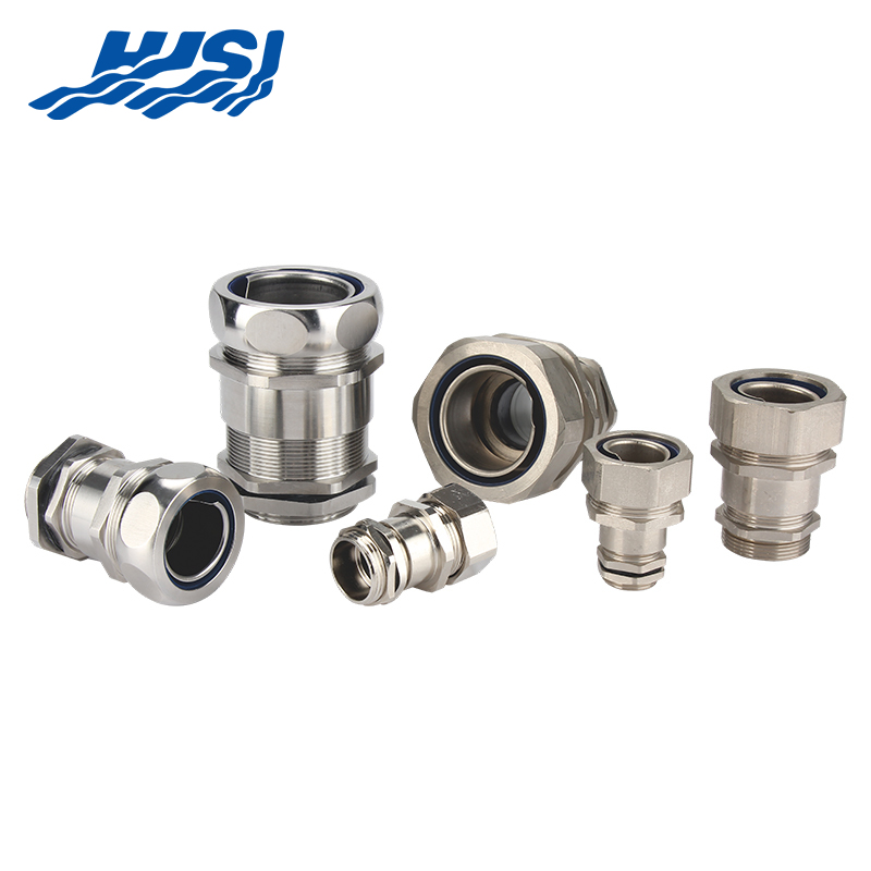
Threaded metallic couplings offer stiffness and a ready path for grounding. Compression couplings squeeze a ferrule around the raceway to make a moisture seal. Push-fit couplings use internal fingers or gaskets that grip as the tube is inserted. Transition couplings join two different raceway types—say, a coated steel segment rising out of a trench to a PVC-coated segment on an above-ground rack. Expansion couplings contain a sliding sleeve or bellows that accepts length change. Angle connectors and tee bodies create direction changes without field bending. Each family has variants for indoor dry locations, for direct burial, for exposure to sunlight, or for use inside plenums where a low-smoke formulation may be required. Selection balances pull-out strength, ease of assembly, repair access, and material compatibility with the surrounding metalwork or concrete.
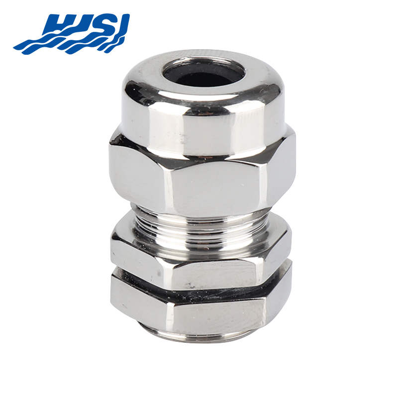
Steel, aluminum, or brass castings provide high impact resistance and long fatigue life. A zinc or epoxy layer delays oxidation. Where the coupling face meets the raceway end, a smooth bore prevents wire insulation from being sliced during pulling. Sharp edges inside a coupling are a common source of field call-backs; factories address this by reaming and chamfering before the coating is applied. On towers, threaded couplings are often installed with a thread sealant that remains pliable, allowing future disassembly for conductor replacement. Metallic couplings contribute to the equipment grounding system, but only if the joint remains tight; therefore, crews check torque after the first week of service and again at annual intervals.
| Feature / Component | Description / Purpose |
|---|---|
| Material Selection | Steel, aluminum, or brass castings provide high impact resistance and long fatigue life |
| Protective Coating | Zinc or epoxy layer delays oxidation |
| Smooth Bore | Prevents wire insulation damage during pulling |
| Reaming & Chamfering | Removes sharp edges inside couplings to reduce field call-backs |
| Threaded Couplings | Applied with pliable thread sealant for future disassembly |
| Grounding & Torque Check | Metallic couplings contribute to grounding if tight; torque checked after 1 week and annually |
PVC, nylon, fiberglass-reinforced polyester, and other non-metallic compounds eliminate galvanic action and reduce weight. A typical non-metallic coupling weighs one-third of its metallic peer, a noticeable benefit when a crew carries hundreds of pieces across a solar field. UV-stabilized black carbon or titanium dioxide is blended into the resin so the coupling surface does not chalk or craze. Because the coupling itself is non-conductive, an internal copper bonding conductor or external jumper must be added if code requires continuous ground. Non-metallic tees and elbows often include molded bosses where a bonding screw can be landed, preserving the integrity of the grounding network without relying on the raceway wall.
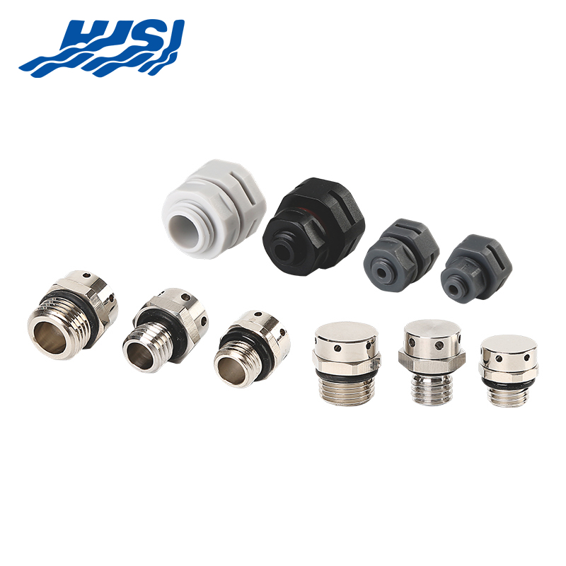
A single droplet that reaches a DC connector inside a combiner box can initiate tracking failure. Couplings intended for outdoor use therefore carry two lines of defense: an elastomeric ring that compresses around the raceway OD, and a threaded or clamped body that prevents the ring from relaxing. Some designs use a tapered throat so the ring is squeezed inward as the body is tightened. Others locate the seal at the very mouth of the coupling, allowing any condensation inside the raceway to drain away from the joint. Installers wipe dust from the raceway end before insertion; a single grain of grit under the seal can create a capillary path. After assembly, a tug test confirms the tube cannot be pulled free, and a visual check verifies the seal is evenly seated.
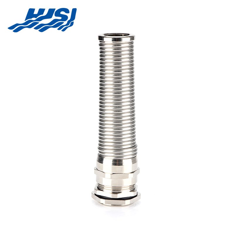
A straight run exposed to full sun can change length by several centimetres between dawn and midday. If the run is anchored at both ends, that movement concentrates at the weakest joint. Expansion couplings are placed at predictable intervals, usually near fixed points such as combiner boxes or inverter skids. A sliding sleeve inside the coupling permits axial motion while an O-ring maintains the environmental seal. The raceway is strapped with expansion clips that allow longitudinal glide but restrain lateral drift. Design handbooks provide spacing tables based on the coefficient of linear expansion of the raceway material and the expected temperature swing for the latitude and mounting method. Field crews paint a witness mark across the coupling halves; during maintenance walks, any offset in the mark reveals that movement has occurred and the expansion coupling is functioning.
Tower vibration is low amplitude but high cycle count. A coupling that loosens by even a quarter-turn can begin to fret: the raceway end pounds against the coupling throat, coating wears away, and moisture enters. Threaded metallic couplings are therefore often installed with a nylon insert lock or a double-nut jam. Where conduit passes through a platform deck, a resilient grommet is fitted so the tube can flex slightly without hammering the edge. On offshore towers, duplex nickel-chrome plating over brass gives extra salt-spray resistance. Inspection protocols include a simple wrench check: if the coupling can be tightened further by hand, it was already loose and is re-torqued to spec.
Battery racks release a small amount of heat and, in some chemistries, trace gases. Connectors inside the container must not outgas substances that could fog sensor windows or corrode copper bus. Manufacturers select thermoplastic blends rated for elevated temperature and low halogen emission. Seals are made from fluorocarbon or silicone rubber that resists swelling. Because containers may be shipped with wiring in place, couplings are taped or locked to prevent loosening during transit. Once on site, the container is positioned, leveled, and the raceway is connected to external pull boxes through vapor-proof transition couplings. A pressure test with an inert gas verifies that the seal remains intact after the container walls have been subjected to transport shocks.
Trenches are rarely uniform. One section may cut through sand, another through cobbles. A coupling buried in cobbles sees point loads that do not exist in sand. Installers bed the raceway in sifted soil or sand free of rocks larger than a thumbnail. A concrete cap may be poured over high-traffic crossings. Couplings rated for direct burial have extra wall thickness and a smooth outer contour so sharp stones are deflected. Where the raceway exits the soil to rise into a combiner box, a seal fitting prevents water from wicking up the interior. The first strap above grade is placed within a hand-span of the coupling so frost heave cannot lever the raceway sideways.
Rooftop arrays move slightly as the building flexes and as thermal expansion shifts ballast blocks. Connectors near roof penetrations are chosen for their ability to tolerate a small angular misalignment without cracking. A parapet junction box may sit on a standoff post; the raceway enters through an expansion coupling that allows vertical motion while the parapet itself moves. Roofing membrane manufacturers specify a minimum clearance between any metal edge and the membrane, so coupling bodies are wrapped with an additional UV-resistant sleeve to prevent abrasion where contact is unavoidable. Ballasted racks often include a cable tray; transition couplings then shift from tray to conduit at the point the circuits leave the array field and drop toward the inverter station.
A large site may begin with metallic conduit underground and switch to non-metallic above ground to save weight or to avoid magnetic heating. At the transition, a grounding bushing or lug plate bonds the equipment grounding conductor between the two raceway types. The transition coupling itself is chosen with an integral grounding terminal so the jumper is not an afterthought. Torque specifications for the terminal follow the same values used for panelboard lugs, ensuring the joint will carry fault current without melting. Periodic resistance measurements are taken with a milli-ohmmeter; any rise above the baseline signals corrosion or loosening inside the coupling.
A repeatable sequence reduces installation time and error rates. Crews stage couplings in color-coded bins: blue for straight, yellow for expansion, red for angle. A battery-powered driver with a calibrated clutch prevents over-tightening of compression rings. A deburring tool removes the sharp inner edge left by the cut-off wheel; the shaving is captured in a cloth pouch so it cannot fall into the raceway.
| Step / Tool | Description / Purpose |
|---|---|
| Color-Coded Bins | Blue: straight couplings, Yellow: expansion, Red: angle; simplifies staging and reduces errors |
| Battery-Powered Driver | Calibrated clutch prevents over-tightening of compression rings |
| Deburring Tool | Removes sharp edges from cut pipe; shavings captured in pouch to prevent contamination |
| Repeatable Sequence | Streamlines installation and minimizes mistakes |
A spacer jig holds the raceway ends at the correct gap while the coupling is rotated into place, ensuring the expansion sleeve is centered. After the final strap is tightened, a bar-code label is wrapped around the coupling; the label is scanned with a tablet that uploads GPS coordinates and time-stamp to the project database, creating a digital twin for future maintenance.
Visual inspection remains the first line of defense. A checklist includes: seal fully seated, threads engaged at least three turns, coupling body free of cracks, witness marks aligned. A low-voltage continuity test confirms metallic couplings are bonded. A high-pot test between conductor and raceway verifies no inadvertent short was created during assembly. On critical runs, an endoscopic camera is inserted through a pull port to inspect the interior of randomly chosen couplings; any scoring or melt mark indicates the pulling lubricant was insufficient or the stringing tension too high. Results are logged, and if a pattern appears, the crew receives refresher training before the next block is installed.
Solar fields may be walked quarterly, wind towers annually, battery containers monthly. Inspectors carry a torque key with a preset clutch; any coupling that accepts more than an eighth-turn is marked for re-torque and re-check in thirty days. Photos are taken of coupling faces and uploaded to a cloud folder tagged by inverter block or turbine ID. Over years, the folder becomes a time-lapse record of UV fading, seal compression set, or coating erosion, allowing asset managers to forecast replacement budgets. When a coupling is replaced, the old piece is tagged with a QR code linking to the work order, preventing it from being accidentally reinstalled elsewhere.
Decommissioning a thirty-year solar farm yields mountains of aluminum and copper, but also thousands of polymer couplings. Modern recycling streams can accept nylon or PVC if metal inserts are removed. Crews slice the coupling body with a battery-powered shear, pop out the brass thread, and drop the pieces into separate drums. Steel couplings are sent to a shredder where coatings are burned off and the metal is remelted. Transport costs are reduced by baling light-gauge raceway and nesting couplings inside one another. Landfill diversion rates above ninety percent are common, supporting the circular economy narrative that renewable energy projects promote.
Civil crews finish grading, electrical crews follow with conduit, then civil return to backfill. A buffer zone of two conduit straps is left exposed so the second civil pass does not crush fresh couplings. Tower erectors install internal raceway as sections are lifted; the electrical crew stands on an adjacent platform to verify coupling torque before the next tower slice obscures the joint. Battery containers arrive pre-wired; the field team supplies pull ropes through external couplings so factory and site raceways can be joined without re-pulling conductors. Weekly interface meetings use a shared model viewed on tablets; clashes between coupling locations and structural clips are resolved before either trade mobilizes.
Researchers are prototyping shape-memory polymer rings that expand when heated, allowing a coupling to be removed without tools during major overhaul. Pilot projects are testing composite raceway with embedded fiber-optic strands; the connector houses a micro-mirror that reflects light, enabling a handheld unit to confirm joint integrity from one end of the line. Regulatory groups are drafting language that would permit recycled-content resins in exposed locations if UV additives meet new exposure tests. Asset insurers now offer reduced premiums if digital torque records are uploaded within twenty-four hours of installation, accelerating adoption of cloud-connected tools.
A site in a high-saline lagoon learned that a common coated-steel coupling lasted half the projected life; switching to a nickel-plated variant at mid-project prevented hundreds of mid-life replacements. A rooftop array in a cold climate found that snow sliding off a standing-seam roof acted like a blade, shearing above-ground couplings; relocating the raceway to the shaded wall eliminated the issue. A wind farm noted that couplings installed during the night shift had a higher loosening rate; the cause was traced to cooler temperatures that stiffened sealing rings, leading to incomplete seating. Requiring a pre-warming blanket for seals solved the problem. These small observations, captured in daily reports, feed back into design guides and training modules, steadily raising the reliability of the next wave of installations.
Every connector produced by Zhejiang HJSI Connector Co., Ltd. has been subjected to rigorous testing—enduring exposure to ultraviolet arc lamps, the corrosive environment of salt spray chambers, and the extreme conditions of thermal cycling test benches. Within our in-house precision mold workshop, threads are machined to micron-level tolerances; subsequently, the connector bodies are immersed in a multi-layer, specialized coating to ensure they can withstand both the saline corrosion found in underground trenches and the ozone-induced oxidation prevalent in rooftop environments. Packed within every carton lies this quiet yet profound professionalism—a dedication deeply embedded in every single product manufactured by Zhejiang HJSI Connector Co., Ltd.

2nd Floor, Building 2, No. 188, Punan 3rd Road, Economic Development Zone, Yueqing City, Wenzhou City, Zhejiang Province, China

Copyright @ Zhejiang HJSI Connector Co., Ltd. All rights reserved.

China Waterproof Breathable Valve Manufacturer
 +86-15858552966
+86-13356176555
+86-15858552966
+86-13356176555

 English
 русский
 عربى
عربى